E. Lawrey
Electrical and Computer Engineering
James Cook University, Douglas Campus, Townsville, Queensland, 4814,
Australia
Email: Eric.Lawrey@jcu.edu.au
|
Published: Fifth International Symposium on Signal Processing
and its Applications,
ISSPA 99, Brisbane, Australia, 22-25 August, 1999
Organised by the Signal Processing Research Centre, QUT, Brisbane,
Australia
|
Abstract
This is paper outlines some of the potential advantages of multiuser OFDM.
An overview of several new techniques that improve system reliability and
spectral efficiency are presented. These include adaptive modulation, adaptive
frequency hopping, and multiple transmitter cells. A low bandwidth hardware
implementation is also presented.
1 Introduction
OFDM has been widely used in broadcast systems. It is being used for Digital
Audio Broadcasting (DAB) [1] and for Digital Video Broadcasting (DVB) in
Europe and Australia. It was selected for these systems primarily because
of its high spectral efficiency and multipath tolerance. OFDM transmits
data as a set of parallel low bandwidth (100 Hz - 50 kHz) carriers. The
frequency spacing between the carriers is made to be the reciprocal of
the useful symbol period. The resulting carriers are orthogonal to each
other provided correct time windowing at the receiver is used. The carriers
are independent of each other even though their spectra overlap. OFDM can
be easily generated using an Inverse Fast Fourier Transform (IFFT) and
received using a Fast Fourier Transform (FFT). High data rate systems are
achieved by using a large number of carriers (i.e. 2000-8000 as used in
DVB). OFDM allows for a high spectral efficiency as the carrier power,
and modulation scheme can be individually controlled for each carrier.
However in broadcast systems these are fixed due to the one way communication.
In most communication systems two-way communications is required and
multiple users must be supported. OFDM can be applied in a multiuser application
producing a highly flexible, efficient communications system. Little work
has been previously done on multiuser OFDM. It was first presented by Wahlqvist
[2] who suggested one possible implementation. The system design of a multiuser
OFDM system is dependent on the intended application and hardware complexity.
This paper presents multiuser OFDM in a more general form and outlines
some of the potential techniques that could be used to make it a highly
efficient and reliable communication system. Additionally a test hardware
solution is presented using SHARC® Digital Signal Processors (DSP)
demonstrating the feasibility of a simple multiuser OFDM system.
2 Adaptive modulation
Most OFDM systems use a fixed modulation scheme over all carriers for simplicity.
However each carrier in a multiuser OFDM system can potentially have a
different modulation scheme depending on the channel conditions. Any coherent
or differential, phase or amplitude modulation scheme can be used including
BPSK, QPSK, 8PSK, 16QAM, 64QAM, etc. Each modulation scheme provides a trade
off between spectral efficiency and the bit error rate. The spectral efficiency
can be maximised by choosing the highest modulation scheme that will give
an acceptable Bit Error Rate (BER). In a multipath radio channel, frequency
selective fading can result in large variation in the received power of
each carrier. For a channel with no direct signal path this variation can
be as much as 30 dB in the received power resulting in a similar variation
in the SNR. Using adaptive modulation the carrier modulation is matched
to the SNR, maximising the overall spectral efficiency.
In systems that use a fixed modulation scheme the carrier modulation
must be designed to provide an acceptable BER under the worst channel conditions.
This results in most systems using BPSK or QPSK. These give a poor spectral
efficiency (1-2 bits/s/Hz) and provide an excess link margin most of the
time. Using adaptive modulation, the remote stations can use a much higher
modulation scheme when the radio channel is good. Thus as a remote station
approaches the base station the modulation can be increased from 1 bits/s/Hz
(BPSK) up to 4-6 bits/s/Hz (16QAM - 64QAM), significantly increasing the
spectral efficiency of the overall system. Preliminary results show that
for a cellular network the system capacity can potentially be doubled using
adaptive modulation.
There are several limitations with adaptive modulation. Overhead information
needs to be transferred, as both the transmitter and receiver must know
what modulation is currently being used. Also as the mobility of the remote
station is increased, the adaptive modulation process requires regular
updates, further increasing the overhead.
There is a trade off between power control and adaptive modulation.
If a remote station has a good channel path the transmitted power can be
maintained and a high modulation scheme used (i.e. 64 QAM), or the power
can be reduced and the modulation scheme reduced accordingly (i.e. QPSK).
Distortion, frequency error and the maximum allowable power variation
between users limit the maximum modulation scheme that can be used. The
received power for neighbouring carriers must have no more than 15-30 dB
variation at the base station, as large variations can result in strong
signals swamping weaker carriers. Intermodulation distortion (IMD) results
from any non linearites in the transmission. This IMD causes a higher noise
floor in the transmission band, limiting the maximum SNR to typically 30-60
dB. Frequency errors in the transmission due to synchronisation errors
and Doppler shift result in a loss of orthogonality between the carriers.
A frequency offset of only 1% of the carrier spacing results in the effective
SNR being limited to 30 dB [4]. The limited SNR restricts the maximum spectral
efficiency to approximately 5-7 bits/s/Hz.
Adaptive modulation requires accurate knowledge of the radio channel.
Any errors in this knowledge can result in large increases in the BER,
due to the small link margin used. For a multiuser OFDM system, transmitting
pilot tones or reference symbols can perform channel characterisation.
Transmitting a symbol with known data allows the phase error to be estimated,
giving the SNR of each carrier. This SNR can then be used to select the
modulation scheme
3 User allocation
There are several methods for allocating carriers to users. The main three
groups are grouped carriers, spread out carriers and adaptive carrier allocation.
3.1 Grouped carriers
The simplest scheme is to group the carriers allocated to each user. Grouping
carriers minimises inter-user interference due to distortion, power level
variation and frequency errors. However, grouping the carrier makes the
transmission susceptible to fading, as the whole group of carriers can
be lost in a null in the spectrum. This problem can be partly overcome
by frequency hopping the carriers. In user allocation scheme described
by [2], groups of carriers are transmitted in short time blocks. These
blocks were randomly frequency hopped to ensure that the time period spent
in a null would is relatively short, approximately 11 symbols. To recover
data lost during a null, time interleaving and forward error correction
was used. These come at the cost of reduced capacity and an increased delay.
3.2 Adaptive Frequency Hopping
A new adaptive hopping technique is proposed such that carrier block hopping
is based on the channel conditions. After the radio channel has been characterised
each user is allocated carriers which have the best SNR ratio for that
user. Since each user will be in a different location the fading pattern
will be different for each remote station. The strongest carriers for one
user are likely to be different from other users. Thus most users can be
allocated the best carriers for them with minimal clashes.
Preliminary studies have shown that adaptive hopping can provide a dramatic
improvement in received power (5-20dB) in a frequency selective channel.
Adaptive hopping virtually eliminates frequency selective fading.
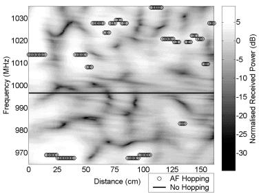
Figure 1. Single User Adaptive Frequency Hopping
Figure 2. Received power verses distance travelled for Adaptive
Frequency Hopping and for a fixed frequency.
Figures 1 and 2 show results for a single user adaptive frequency hopping
system. The radio channel model used for this experiment was measured for
a link between two rooms in the Electrical and Computer Engineering building
at JCU. The transmitter and receiver were spaced 24 m apart. Figure 1 shows
simulated adaptive frequency hopping for this measured radio channel. For
the No Hopping case the frequency used was fixed and thus a straight line
on figure 1. The bandwidth allocated to the user was 1% of the system bandwidth.
The user was allocated the strongest frequency band and the frequency allocation
was updated every 5 cm. Figure 2 shows for the same measured channel the
received power for the adaptive frequency hopping receiver and for one
which has no hopping. The adaptive hopping receiver suffers much less fast
fading and has a much greater average power level than when no hopping
was used.
In a multipath channel the frequency response of the channel will change
significantly in 15 cm at 1 GHz. It is therefore important that the frequency
update rate is much faster than every 15 cm moved. Typically an update
distance of 5 cm is sufficient. At a velocity of 60 km/Hr this results
in an update rate of 330 times per sec. The overhead for the frequency
hopping will depend on the user data rate, the number of users, and whether
the system is a full, or half duplex system.
For a full duplex system the transmitter and receiver frequency are
offset from each other by >40 MHz to allow for isolation between them.
For this type of transmission the number of radio channels that must be
characterised is 2N, where N is the number of users. The number of reference
symbols that must be transmitted is N+1, one from the base station in the
forward link and one from each user. This can be reduced by transmitted
a comb pattern, allowing typically 20 users to be characterised per reference
symbol. However for a 10MHz system BW, full duplex system with 100 users
at 50kbps each (QPSK average) and using a comb characterisation, the overhead
will be 30-50% of the data capacity.
This overhead can be reduced by using a time division half-duplex system.
If both the forward and reverse links use the same frequency, then only
one reference symbol is needed. A single reference symbol transmitted by
the base station is received by all remote stations, allowing characterisation
of all forward links. Due to the reciprocal nature of radio channels the
transfer function of the reverse link will be the same as the forward link.
Regardless of how the radio channels are characterised the number of frequency
re-allocations will be proportional to the number of users. The overhead
for a half-duplex system as described above will only be 10-15%.
Adaptive frequency hopping reverts to normal random hopping when the
velocity is too high for the hopping to keep up with the rate of change
of the channel. Fortunately this occurs at high velocity and consequently
the coherence time of the fading is very small. Time interleaving and forward
error correction can be used to overcome these fading periods and since
the fade time is short, the time interleaving length required is also short,
resulting in minimal delay.
Adaptive hopping comes at the cost of increasing the complexity of the
transmitter and receiver. Additionally adaptive hopping is less useful
at high velocities over 30 km/Hr.
3.3 Comb Spread Carriers
Carriers can be allocated in a comb pattern, spreading them over the entire
system bandwidth. This improves the frequency diversity, preventing all
the carriers used by a user being lost in a null in the spectrum. However,
this allocation scheme may be susceptible to inter-user interference. This
type of user allocation is useful in applications that can not use adaptive
hopping. Figure 3 shows an example of a comb user carrier allocation.
Figure 3. Reverse link of a multiuser OFDM system
4 Multiple Transmitter Cells
ODFM signals are intrinsically multipath robust due to the low symbol rate
used and the addition of a time domain guard period [3]. Multipath reflections
that have a delay spread less than the guard period cause no inter-symbol
interference. This allows for Single Frequency Networks (SFN) to be used
in broadcast OFDM systems [1]. A single frequency can be used for all transmitters
in a country wide broadcast. For DAB the transmitter can be spaced up to
75 km apart. Normally each transmitter must use a different frequency from
neighbouring transmitters, as they would appear as strong multipath if
the same frequency were used. A SFN greatly reduces shadowing as multiple
signals are received from different directions resulting in spacial diversity.
The concept of a SFN can be applied to a multiuser OFDM system. The
base station would consist of multiple repeaters transmitting the same
signal. Each signals received by the repeaters can either be combined and
decoded with a single central receiver, or each repeater could have its
own receiver. Using a multiple transmitter cell will significantly reduce
shadowing due to the increased spacial diversity, as shown in figure 4.
Figure 4. Reduced shadowing with a multiple transmitter cell
Multiple transmitter cells are particularly suitable for wireless LAN
applications. Shadowing makes it difficult to achieve good coverage of
a building. Repeaters are often required, except that in conventional systems
these repeaters cause multipath problems. In a multiuser OFDM system repeaters
could be added where needed, with no additional problems. A multiple transmitter
cell could be as simple as a coax running the length of a building corridor
with multiple tap off points (see figure 5).

Figure 5. Simple Multiple Transmitter Set up for Wireless LAN
5 Hardware implementation
A small-scale test system was made using Analog Devices Ez-Kit evaluation
boards. This board includes a 40 MHz SHARC® DSP processor, a 16 bit
stereo CODEC, bootloader kernel, and a serial interface. A baseband multiuser
OFDM system was implemented using the on- board CODECs. The maximum sample
rate for the CODECs was 48 kHz. A 512 point real FFT was used for signal
generation, of which 196 carriers were active, giving a bandwidth of 18
kHz. A guard period of 32 samples was used. Each transceiver was made using
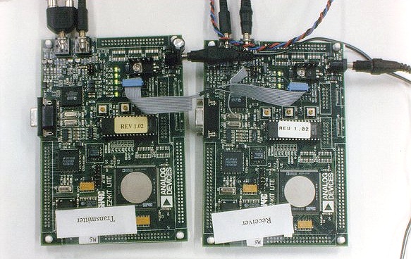
two Ez-kit boards. Figure 6 shows one of the multiuser OFDM transceivers.
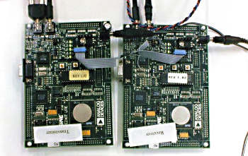
Figure 6. Example Multiuser OFDM transceiver
Figure 7. Separated spectrum of the reverse link for the multiuser OFDM test system
5.1 User Allocation
A three user system was made consisting of a base station and two remote
stations. The forward link transmission was subdivided into 2 groups of
96 carriers, one group for each user. The reverse link transmission from
each remote station was a group of 96 carriers. One remote station used
the lower 96 carriers, the other the upper 96 carriers. No adaptive frequency
hopping was used.
5.2 Carrier Modulation
The input data for each user was an audio signal sampled at 8 kHz at 8
bits. This data was modulated with 256 PSK, using a linear mapping from
the 8 bit audio data. Due to the linear mapping errors in reception have
only a small effect. The modulation was fixed to simplify the system.
5.3 Time Synchronisation
Multiuser OFDM requires strict time and frequency synchronisation. In the
reverse link the signals from all users are combined in the channel and
are received as a complete OFDM signal. All remote stations must be frequency
and time synchronised in order for the transmitted signals to remain orthogonal
to each other. All signals in the forward channel originate from the base
station, and thus synchronisation techniques developed for broadcast OFDM
can be used [3, 4].
The remote stations were synchronised to the base station using a null
symbol frame synchronisation. The base station transmitted a null symbol
at the start of each frame (36 symbols). The remote stations synchronised
to the null using a moving average envelope detector.
5.4 Results
The mobile system was found to work, with no apparent cross talk between
the two users. The forward link synchronisation was found to be stable,
with an error of ~1-2 samples/frame at a high SNR, degrading to 8-32 samples
at a SNR of 1dB. Reverse link synchronisation was slightly worse caused
by difference in forward synchronisation of the two users.
6 Conclusion
This paper has presented an overview of multiuser OFDM and some of the
new techniques that can enhance system performance. Multiuser OFDM allows
for highly flexible communications, thus can be made to adapt to radio
channel conditions. This adaptability results in a high spectral efficiency
and reliability.
References
[1] Thibault L. and Le M.T., "Performance Evaluation of COFDM for Digital
Audio Broadcasting, Part I: Parametric Study", IEEE Transactions on
Broadcasting, Vol. 43, No. 1, pages 64-75, March 1997
[2] Wahlqvist M., Östberg C., Beek J., Edfors O., Börjesson
P., "A Conceptual Study of OFDM-based Multiple Acess Schemes", Technical
Report Tdoc 117/96, ETSI STC SMG2 meeting no 18, Helsinki, Finland, May
1996, http://www.sm.luth.se/csee/sp/publications/
[3] Lee D., Cheun K., "A new symbol timing recovery algorithm for OFDM
systems", IEEE Transactions on Consumer Electronics, Vol. 43, No.
3, pages 766-775, August 1997
[4] Moose P., "A Technique for Orthogonal Frequency Division Multiplexing
Frequency Offset Correction", IEEE Transactions on Communications,
Vol. 42, No. 10, pages 2908-2914, October 1994
|